USB LED Matrix 8x8: Unterschied zwischen den Versionen
Zur Navigation springen
Zur Suche springen
| Zeile 25: | Zeile 25: | ||
<gallery caption="Pics" widths="250px" heights="250px" perrow="3"> | <gallery caption="Pics" widths="250px" heights="250px" perrow="3"> | ||
| − | File: usb_led_matrix_8x8_prototype.jpg | Prototyp mit 4 | + | File: usb_led_matrix_8x8_prototype.jpg | Prototyp mit 4 angeschlossenen LED's (2 Reihen, 2 Spalten) am Steckbrett aufgebaut |
File: usb_led_matrix_8x8_box_1.jpg | Leeres Gehäuse mit PCB Halterungen | File: usb_led_matrix_8x8_box_1.jpg | Leeres Gehäuse mit PCB Halterungen | ||
File: usb_led_matrix_8x8_box_2.jpg | Offenes Gehäuse mit PCB | File: usb_led_matrix_8x8_box_2.jpg | Offenes Gehäuse mit PCB | ||
| Zeile 37: | Zeile 37: | ||
[[Media:led_matrix_usb.tar.gz]]<br> | [[Media:led_matrix_usb.tar.gz]]<br> | ||
[[Media:led_matrix_usb_box.tar.gz]] | [[Media:led_matrix_usb_box.tar.gz]] | ||
| + | |||
| + | [[Category: PCB]] | ||
Version vom 4. Juni 2011, 14:17 Uhr

Eine 2 farbige (rot, grün, [orange]) 8x8 Led Matrix, die über eine Software USB Implementierung angesteuert wird.
Layouteditor
Eagle 5.7.0 Light Edition
Verwendete Libaries: SparkFun.lbr (http://www.opencircuits.com/SFE_Footprint_Library_Eagle)
Gehäuse

Basis wurde mit JBOX erstellt. Mit QCad wurde dann die USB Buchse und die LED Matrix ausgeschnitten.
Software
Aktuelle Software befindet sich im GIT repository:
- doc/: Schaltplan und Gehäuseplan
- host/: Host Software (C++, Qt)
- src/: µC firmware
Gallery
- Pics
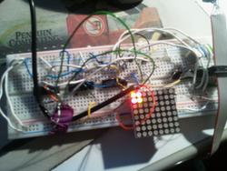
Prototyp mit 4 angeschlossenen LED's (2 Reihen, 2 Spalten) am Steckbrett aufgebaut
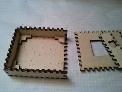
Leeres Gehäuse mit PCB Halterungen
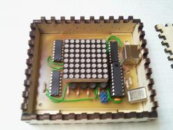
Offenes Gehäuse mit PCB
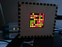
Random Animation
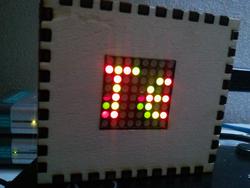
Lauftext (Durch das Multiplexen entstehen beim unmittelbaren Wechsel Artefakte, welche die Kamera sieht aber nicht das menschliche Auge)
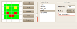
Screenshot der Host Software


