Urban Cricket
Project description
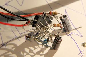
Urban Cricket is a small circuit that imitates the call of a cricket, only being powered by a small solar cell.
The idea comes from Reinhard Gupfinger a Linz based artist I met during the Ars Electronica Festival 2011 in Linz.
This circuit here is a altered version of his original circuit.
A video demonstrating the functionality can be found here: Youtube video
Since it is hard to recreate a circuit not having a pcb an a schematic, people who want to recreate the Urban cricket will find the schematics, a layout to create a pcb and a parts list here.
Schematic description
The Urban Cricket consists of three simple oscillators, a piezo beeper with built in driver and a solar cell for powering the circuit. The piezo beeper has a built in driver which means that a voltage applied will cause the beeper to generate noise not only a short click. It generates a tone at about 2,000 to 3,000 Hertz witch sounds pretty annoying ("piiiiiiiiiiiii").
The first oscillator makes the beeper beep at a variable frequency of about 20-100 Hertz. The beeper controlled by the first oscillator sounds short 2-3khz bursts ("brrrrrrrrrrrrrrrrr")
The second oscillator works much slower at about 1 to 3 Hertz. The functionality of the second oscillator is to stop the first one at some times. Now the cricket sounds "brrr brrr brrr brrr brrr brrr".
The third oscillator runs even slower than the second one causing the second one to stop at some times. Now the cricket sounds "brrr brrr brrr <pause> brrr brrr brrr <pause>" and so on.
The the oscillator stages a coupled via diodes to make them influence the other only one way. All six not-gates a located on one ic-chip (74HC04 or 74HC14).
Values
Well, there are different options how to assemble the circuit. The "original" parts list was:
- R1: 100 k (kilo Ohms)
- R2: 39 k
- R3: 290 k
- C1: 100 nf (nano Farad)
- C2: 10 µf (micro Farad)
- C3: 10 µf
- C4: 100 µF
- D1,D2: 1N4148
- Solar cell: 4V/35mA (part number Conrad Electronic: 191308)
- Beeper (part number Conrad electronic: 710865)
- IC: 74HC14 (6x inverter with Schmitt trigger) or 74HC04 (6x inverter) (part number Conrad electronic: 164232 or 164194)
The bold faced parts can be changed to generate a different tone. Since the use of polarized capacitors for C2 and C3 is kind of unskilled (it works most the times especially when using higher voltage capacitors ie. 63 volts) it is better to use non-polarized capacitors. 10µF non-polarized ones are expensive and or bigger. So much smaller capacitors can be used when increasing the value of the corresponding resistor at the same time.
Other possible Values are:
- R1: 100 k (kilo Ohms)
- R2: 2.2 M (Mega Ohms)
- R3: 22 M
- C1: 100 nf (nano Farad)
- C2: 100 nf
- C3: 100 nf
Or:
- R1: 100 k (kilo Ohms)
- R2: 3.3 M (Mega Ohms)
- R3: 3.3 M
- C1: 100 nf (nano Farad)
- C2: 68 nf
- C3: 560 nf
The values should be matched among the 3 oscillators to prevent "chopping off" a tone (brrrr brrrr brrrr br or Brrrr Brrr B). So the values above are only suggestions of what could sound nice. Try to experiment, maybe use a potentiometer to change the tone on the fly.
Making a PCB
The Image on the right is a 600dpi layout of the PCBs. It is designated to make 18pcs. out of one Euro-PCB (one sided, 100x160mm)
Assembly
- IC: Pin one is marked with a rectangular shaped pad
- Diodes: cathode is marked with a dash on the pad.
- C4: Negative pole is marked with a dash.
Hyperlinks
Credits
Rudi, Christoph, Adrian, Christian
