Arduino voltammeter: Unterschied zwischen den Versionen
| (4 dazwischenliegende Versionen von 2 Benutzern werden nicht angezeigt) | |||
| Zeile 17: | Zeile 17: | ||
and also the Fritzing scheme for closer reference; http://fritzing.org/ | and also the Fritzing scheme for closer reference; http://fritzing.org/ | ||
| − | {{zip|ArduinoAmmeter.zip|118KB| | + | {{zip|ArduinoAmmeter.zip|118KB|}} |
=Resistor Values= | =Resistor Values= | ||
The values of the given resistors are in the breadboard | The values of the given resistors are in the breadboard | ||
picture | picture | ||
| − | (from left to right) 100K, 10K, 0.47 Ohm, 220 Ohm, 100K, 2.2K (twice). | + | (from left to right) 100K, 50K(10K/6.8K), 47(0.47/4.7) Ohm, 220 Ohm, 100K, 2.2K (twice). |
Henceforth, I refer to them as R1, R2, R3, R4, R5, R6 und R7 respectively, | Henceforth, I refer to them as R1, R2, R3, R4, R5, R6 und R7 respectively, | ||
| − | + | The values of R2 and R3 depend from the range you are taking measurement. To decide their proper | |
| − | + | value use the table below. Note that you must adapt also the Arduinocode accordingly; | |
| − | + | R2 refers to variable '''V10K_RESISTOR ''' and R3 is '''I0_47_RESISTOR''' | |
| + | |||
Following table lists different values of R2 and its corresponding maximum voltage; | Following table lists different values of R2 and its corresponding maximum voltage; | ||
| Zeile 46: | Zeile 47: | ||
|} | |} | ||
| − | |||
| − | |||
| − | |||
The value of the resistors R6 und R7 (here given as 2.2K) need not to be exactly like that, | The value of the resistors R6 und R7 (here given as 2.2K) need not to be exactly like that, | ||
| Zeile 73: | Zeile 71: | ||
log permanent OFF | log permanent OFF | ||
| + | |||
| + | =Accuracy= | ||
| + | Alas, the values are not too accurate. Check out discussion and proposals | ||
| + | for bettery accuracy at following link | ||
| + | http://arduino.cc/forum/index.php/topic,140203.0.html | ||
| + | For one thing you can lower the resistor values when it is safe for your | ||
| + | application. | ||
=References= | =References= | ||
Aktuelle Version vom 15. Juli 2014, 21:57 Uhr
For the German version go to Arduino_VoltAmmeter
General
I describe a voltmeter and an ammeter using an Arduino microcontroller, measuring voltage and current simultanenously, all in one circuit. These measurements can be made permanently (for instance every second).
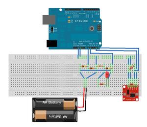
In picture ammeter on breadboard you see at the input a battery block and at the output a LED with its safety resistor. These components can be replaced by any power source and current consumer respectively, as long as they are in a certain range. In following attachment you find the Arduino code, the DS1307 library and also the Fritzing scheme for closer reference; http://fritzing.org/
| ArduinoAmmeter.zip (118KB) [info] |
Resistor Values
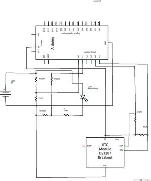
The values of the given resistors are in the breadboard picture (from left to right) 100K, 50K(10K/6.8K), 47(0.47/4.7) Ohm, 220 Ohm, 100K, 2.2K (twice). Henceforth, I refer to them as R1, R2, R3, R4, R5, R6 und R7 respectively,
The values of R2 and R3 depend from the range you are taking measurement. To decide their proper value use the table below. Note that you must adapt also the Arduinocode accordingly; R2 refers to variable V10K_RESISTOR and R3 is I0_47_RESISTOR
Following table lists different values of R2 and its corresponding maximum voltage;
for different values of R3 its maximum current.
Note that R2 and R3 can be chosen independently from
each other. To calculate different values you may use the Libre Office calc file contained
in the archive ArduinoAmmeter.zip.
| R2 | U_max | R3 | I_max | |
|---|---|---|---|---|
| 50K | 15V | 0.47 Ohm | 10.6A | |
| 10K | 55V | 4.7 Ohm | 1060mA | |
| 6.8K | 79V | 47 Ohm | 106mA |
The value of the resistors R6 und R7 (here given as 2.2K) need not to be exactly like that, for instance a value of 4.7K worked as fine. There is nothing to adapt in the code in this case.
Logging
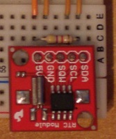
Time and Date information is delivered by DS1307 break out board. You can also omit this part (including cables) without affecting the measurement of voltage and current. Time and Date is then simply shown to be zero in the log entries.
Example (from SERIAL MONITOR)
log permanent on
V=5.86;mA=10.27;R_v=523.30;mW=60.14;time=19:2:58;day=5;monat=2
V=5.86;mA=10.27;R_v=523.30;mW=60.14;time=19:2:59;day=5;monat=2
V=5.86;mA=10.27;R_v=523.30;mW=60.14;time=19:3:0;day=5;monat=2
V=5.86;mA=10.27;R_v=523.30;mW=60.14;time=19:3:1;day=5;monat=2
log permanent OFF
Accuracy
Alas, the values are not too accurate. Check out discussion and proposals for bettery accuracy at following link http://arduino.cc/forum/index.php/topic,140203.0.html For one thing you can lower the resistor values when it is safe for your application.
References
My circuit is an adaption of Renatos blog http://rexpirando.blogspot.com/2011/03/arduino-volt-ammeter-part-1-breadboard.html who himself refers to page http://electronics-diy.com/70v_pic_voltmeter_amperemeter.php, where you can find the kernel circuit doing the measurements.


