Urban Cricket: Unterschied zwischen den Versionen
Cisk (Diskussion | Beiträge) |
Cisk (Diskussion | Beiträge) |
||
| Zeile 7: | Zeile 7: | ||
Since it is hard to recreate a circuit not having a pcb an a schematic, people who want to recreate the Urban cricket will find the schematics, a layout to create a pcb and a parts list here. | Since it is hard to recreate a circuit not having a pcb an a schematic, people who want to recreate the Urban cricket will find the schematics, a layout to create a pcb and a parts list here. | ||
| − | Schematic: | + | Schematic:<br> |
| − | [[Image:Urban-cricket-schematic-simply.gif|500px|Sechematic]] | + | [[Image:Urban-cricket-schematic-simply.gif|500px|Sechematic]]<br> |
Schematic description: | Schematic description: | ||
The Urban Cricket consists of three simple oscillators, a piezo beeper with built in driver and a solar cell for powering the circuit. The piezo beeper has a built in driver which means that a voltage applied will cause the beeper to generate noise not only a short click. It generates a tone at about 2,000 to 3,000 Hertz witch sounds pretty annoying ("piiiiiiiiiiiii").<br> | The Urban Cricket consists of three simple oscillators, a piezo beeper with built in driver and a solar cell for powering the circuit. The piezo beeper has a built in driver which means that a voltage applied will cause the beeper to generate noise not only a short click. It generates a tone at about 2,000 to 3,000 Hertz witch sounds pretty annoying ("piiiiiiiiiiiii").<br> | ||
Version vom 23. September 2011, 19:41 Uhr
Urban Cricket is a small circuit that imitates the call of a cricket, only being powered by a small solar cell.
The idea comes from Reinhard Gupfinger a Linz based artist I met during the Ars Electronica Festival 2011 in Linz.
This circuit here is a altered version of his original circuit.
A video demonstrating the functionality can be found here: Youtube video
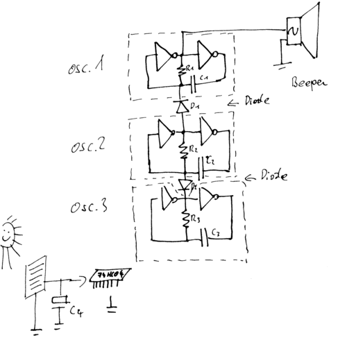
Since it is hard to recreate a circuit not having a pcb an a schematic, people who want to recreate the Urban cricket will find the schematics, a layout to create a pcb and a parts list here.
Schematic:

Schematic description:
The Urban Cricket consists of three simple oscillators, a piezo beeper with built in driver and a solar cell for powering the circuit. The piezo beeper has a built in driver which means that a voltage applied will cause the beeper to generate noise not only a short click. It generates a tone at about 2,000 to 3,000 Hertz witch sounds pretty annoying ("piiiiiiiiiiiii").
The first oscillator makes the beeper beep at a variable frequency of about 20-100 Hertz. The beeper controlled by the first oscillator sounds short 2-3khz bursts.
The second oscillator works much slower at about 1 to 3 Hertz. The functionality of the second oscillator is to stop the first one at some times. Now the cricket sounds "brrr brrr brrr brrr brrr brrr".
The third oscillator runs even slower than the second one causing the second one to stop at some times. Now the cricket sounds "brrr brrr brrr <pause> brrr brrr brrr <pause>" and so on.
The the oscillator stages a coupled via diodes to make them influence the other only one way. All six not-gates a located on one ic-chip (74HC04 or 74HC14).
soon.
